


In architectural practice, not all 3D models are created equal. When discussing 3D modeling types in architecture, professionals are often referring to very different tools, outputs, and objectives under the same umbrella term. Some models are built for visual impact. Others exist to coordinate disciplines, calculate quantities, or document construction intent. Understanding the distinction between geometry and data is the first step in navigating the full spectrum of types of 3D modeling available today.
At a glance, there are four primary approaches: Direct Modeling, Parametric Modeling, BIM Modeling, and Point Cloud Modeling. Each solves a different problem. Moreover, they behave differently under revision. As a result, the deliverables vary significantly across approaches. Ultimately, the right choice depends not on preference, but on project stage, scope, and stakeholder needs.
What Is a 3D Model in Architecture? Geometry vs Data
At its simplest, a 3D model in architecture is a digital representation of a building or space. But that definition hides a critical distinction.
Some models are pure geometry. They describe shape, proportion, surface, and light. These are typically used for rendering, presentations, and marketing. Their strength lies in visual clarity.
Other models are data-rich systems. They contain information about materials, fire ratings, structural properties, cost codes, manufacturer details, and installation logic. These are used for documentation, coordination, and construction management.
This difference fundamentally determines which modeling approach is appropriate.
A common misconception is that BIM equals a 3D rendering model. It does not. BIM models may contain geometry, but their primary purpose is coordination and data management. They are not optimized for photorealistic output without additional processing.
Choosing the wrong type of model for the wrong objective leads to rework, delays, and misalignment between teams.
At-a-Glance: 4 Types of 3D Modeling in Architecture
| Type | Best for | Strengths | Limitations | Typical outputs |
|---|---|---|---|---|
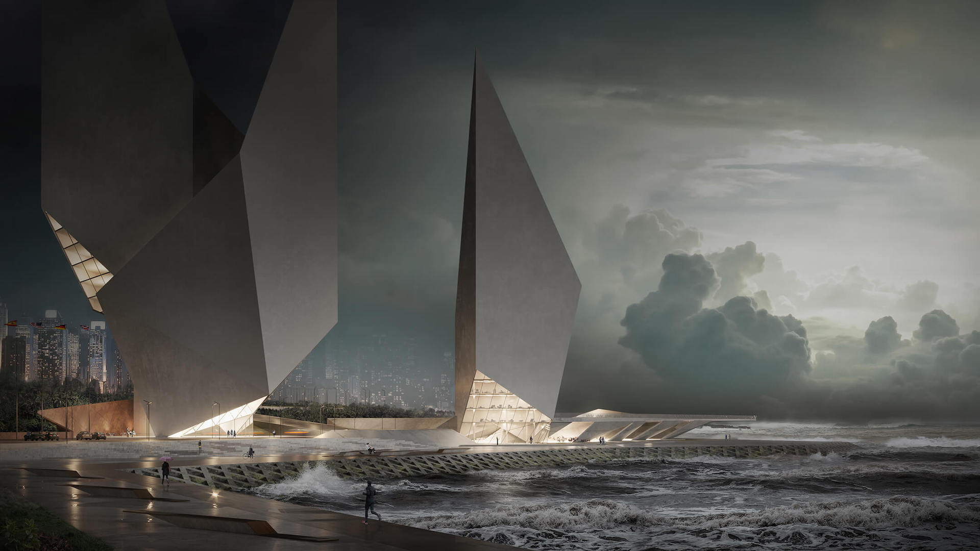
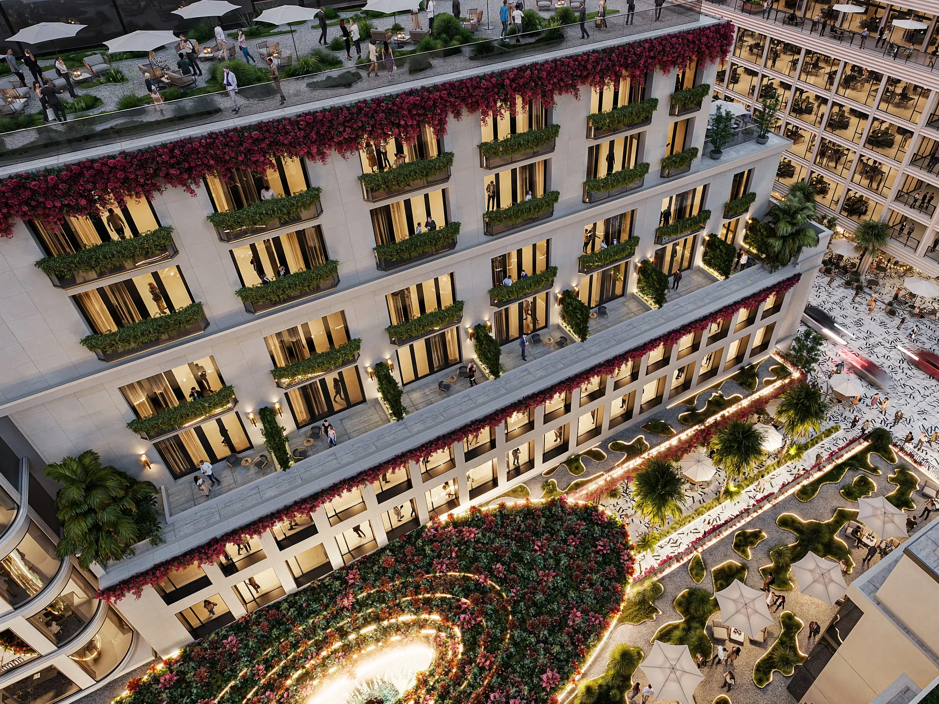
| Direct Modeling | Marketing visuals, concept exploration | Speed, creative freedom, render-ready | Not for documentation; hard to revise systematically | Hero renders, animations, walkthroughs |
| Parametric Modeling | Design optioning, complex geometry | Rule-driven revisions, consistency | Steeper learning curve | Design studies, facade systems, massing options |
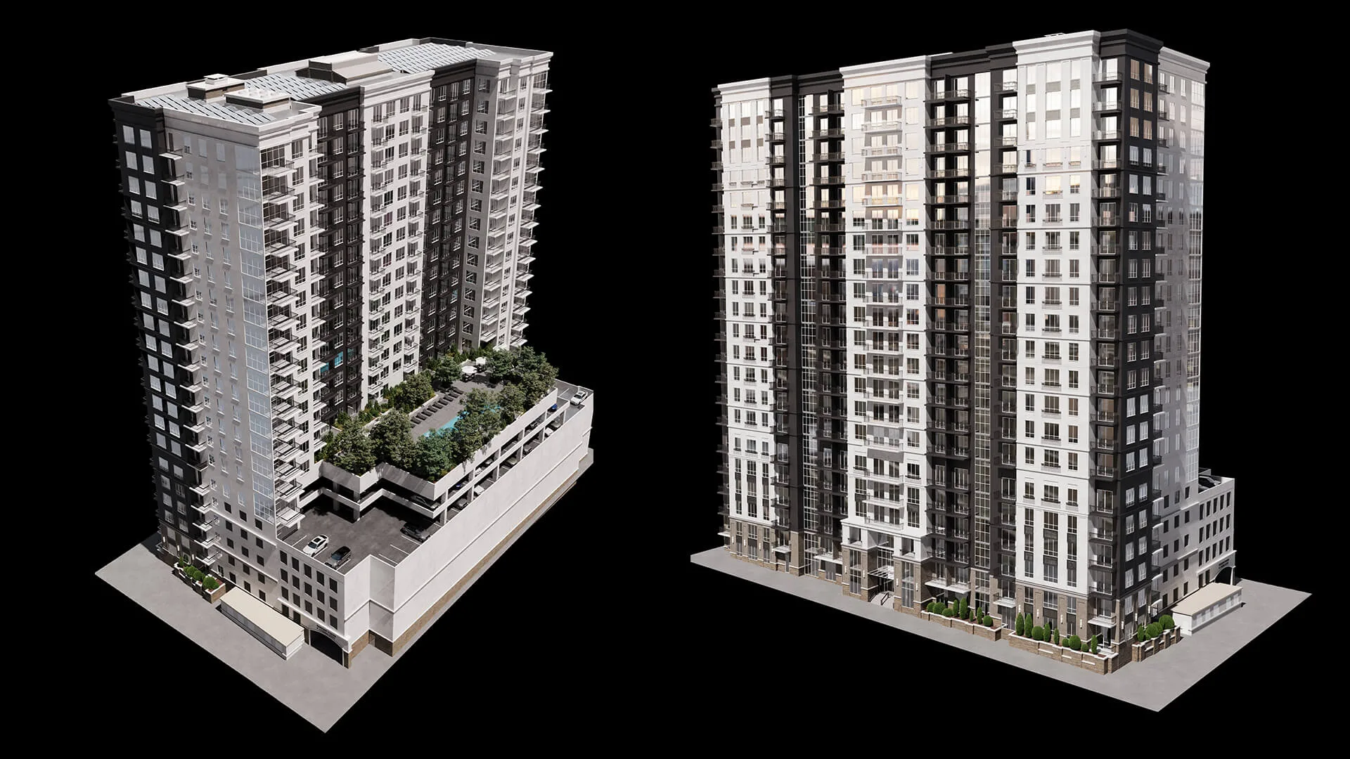
| BIM Modeling | Documentation, coordination, quantities | Data-rich, clash detection, multi-discipline | Not optimized for photorealistic rendering | Construction docs, schedules, IFC files |
| Point Cloud Modeling | Existing conditions, renovation | High accuracy of as-built conditions | Needs processing; occlusion/noise issues | As-built reference, scan-to-BIM input |
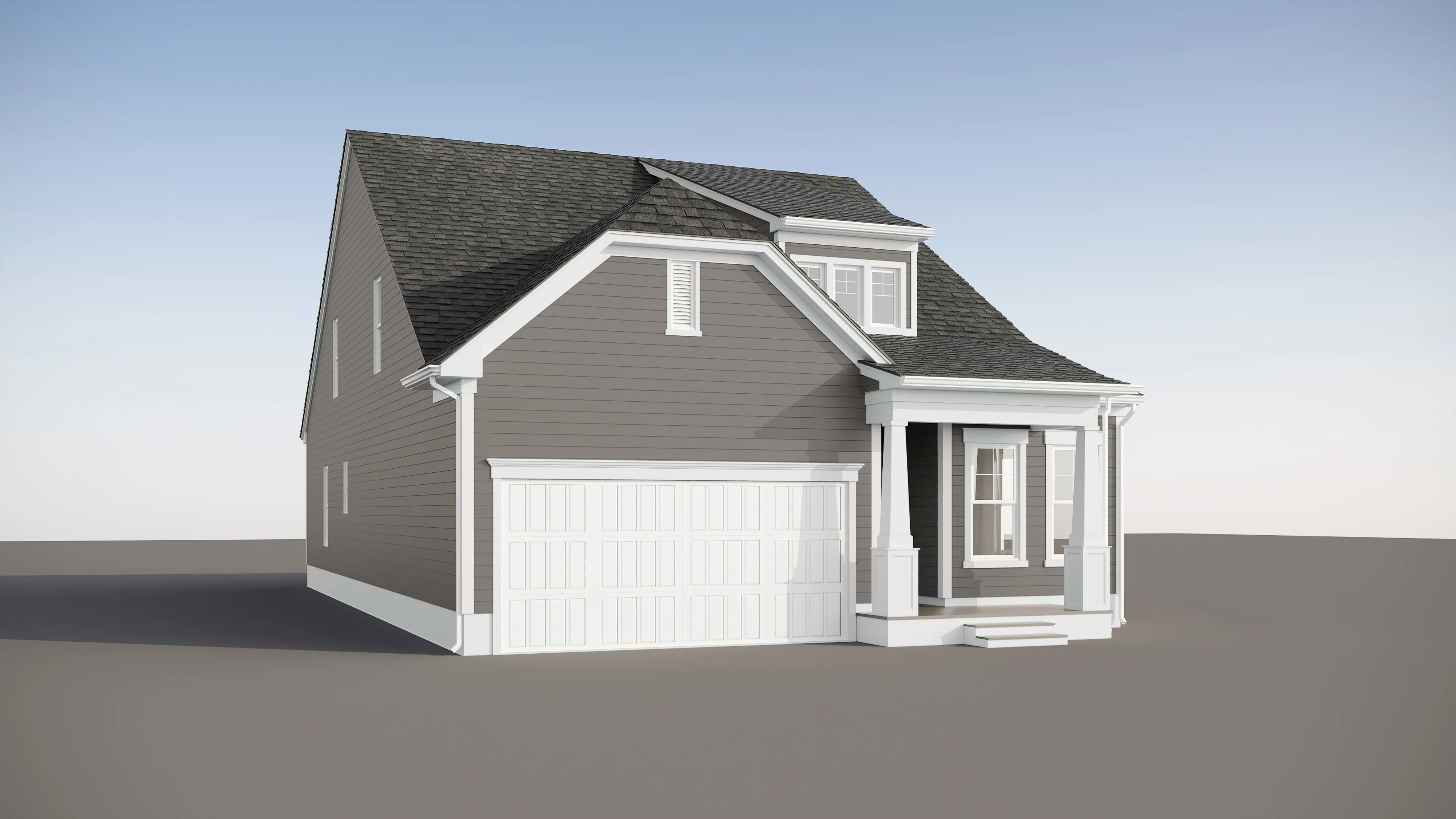
#1. Direct Modeling
Direct modeling is the most intuitive approach. Geometry is built manually, without parametric dependencies. Local edits affect only selected elements. No rule-based cascades are updating the entire model.
This makes it ideal for:
- Marketing visuals
- Concept exploration
- Render-ready assets
It is not ideal for:
- Systematic documentation
- Large-scale coordinated revisions
Typical outputs include hero renders, animations, and interactive tours.
Commonly done in DCC tools such as 3ds Max, Blender, and Maya.
For architectural 3D rendering outputs, this workflow often feeds directly into visualization pipelines:
Primitive Modeling
Primitive modeling begins with base shapes such as cubes, spheres, and cylinders. These serve as starting points for more complex objects.
It is commonly used in early conceptual stages to block out massing quickly. However, primitive-based models usually require refinement before photorealistic rendering.
Polygonal Modeling
Polygonal modeling relies on meshes composed of vertices, edges, and polygons. The mesh structure, known as topology, determines how surfaces behave under smoothing, lighting, and deformation.
Specifically, high-poly models are typically used for still hero images where maximum detail is required. Low-poly or optimized meshes are preferred for animation, real-time environments, and interactive tours.
Architectural examples include facade elements, furniture, and entourage assets.
Curved forms require either increased geometric density or smoothing workflows. This is a trade-off, not an absolute limitation.
Spline / NURBS Modeling
Spline and NURBS-style workflows are curve-driven. They are particularly effective for railings, profiles, moldings, and organic forms.
When used for rendering, these surfaces are often converted to mesh geometry and require UV mapping or retopology for texturing. Conversion is part of the workflow, not a flaw.
Wireframe / CAD — Context Note
Wireframe represents skeletal geometry and often serves as a structural base for further modeling. CAD workflows emphasize precision for technical documentation. These are not standalone modeling philosophies but instrumental methods within broader workflows.
#2. Parametric Modeling
Parametric modeling is rule-based. Instead of manually adjusting geometry, designers define parameters and relationships. Changing one parameter updates all dependent elements.
Examples of parameters include:
- Bay spacing
- Floor-to-floor height
- Facade pattern rules
This approach is best for:
- Design under constraints
- Complex geometries
- Rationalization of systems
Revision behavior is dependency-driven. A single change cascades across the model.
Compared to direct modeling:
- Parametric enables systematic changes
- Direct supports localized edits
Parametricism, popularized by figures like Gehry and Zaha Hadid, demonstrated how rule-based geometry could shape entire architectural languages.
#3. BIM Modeling
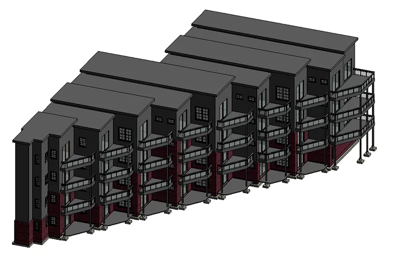
BIM modeling is data-rich. Every element carries information: materials, dimensions, specifications, and performance data.
BIM is not a rendering model. It is optimized for coordination. According to Global Growth Insights (2025), 66% of US architectural firms now use BIM, and 70% of infrastructure tenders require BIM compliance. BIM has been shown to reduce design conflicts by 35% and cut average rework costs by 45%.
Best for:
- Documentation
- Multi-discipline collaboration
- Clash detection
- Cost estimation
- Scheduling
LOD (Level of Detail) significantly affects time and cost. Higher LOD means more modeling effort. LOD should be agreed upon at project start.
Collaboration relies on version control and IFC, an open exchange format.
Stakeholders include general contractors, consultants, clients, and regulatory authorities.
Typical outputs:
- Construction documents
- Schedules
- IFC files
- Coordination models
#4. Point Cloud Modeling
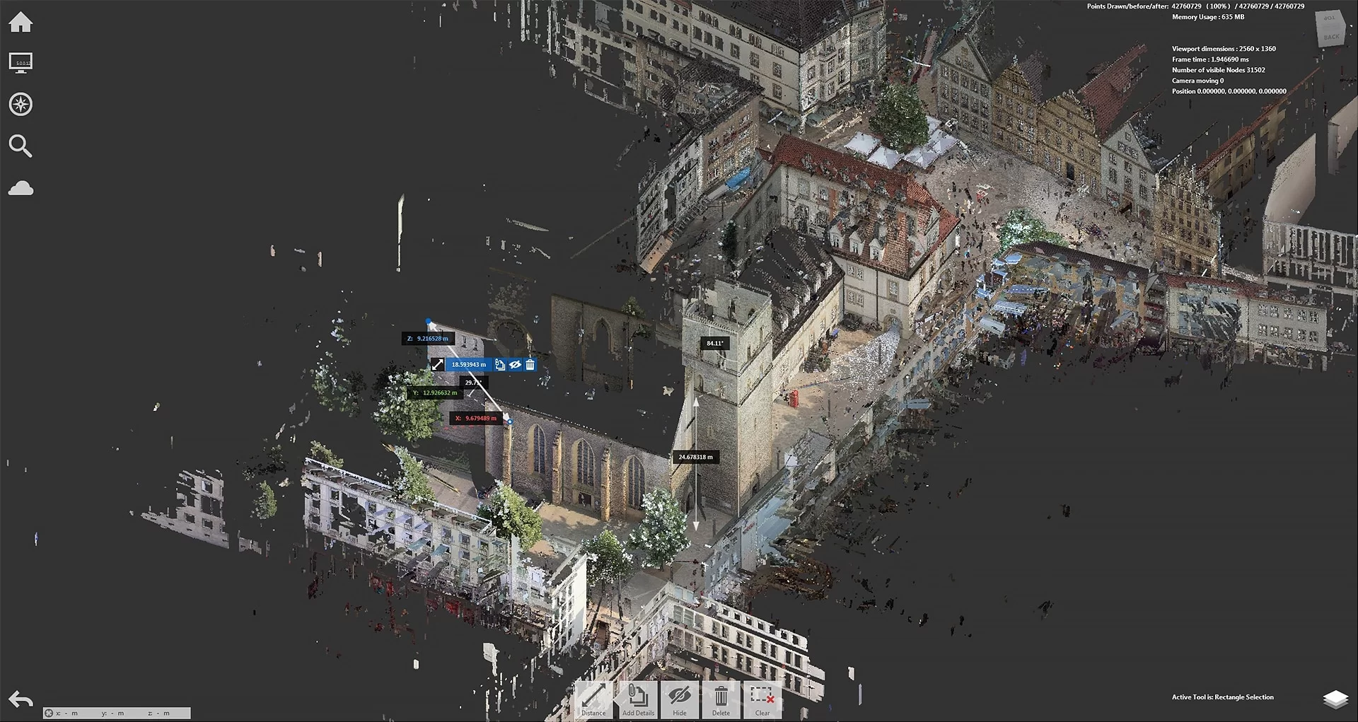
Point cloud modeling begins with laser scanning or photogrammetry of existing structures. The result is a dense collection of 3D points representing physical reality.
Best for:
- Renovation
- Retrofit
- Historical preservation
- As-built documentation
Laser scanning offers high accuracy. Photogrammetry reconstructs geometry from photographic data.
Accuracy depends on proper registration. Occlusion and noise can reduce usability.
Scan-to-BIM
Scan-to-BIM modeling is the process of converting a point cloud into a structured BIM model of existing conditions.
Definition
Scan-to-BIM modeling is the process of converting a point cloud into a structured BIM model that accurately represents existing building conditions. In simple terms, it transforms raw 3D scan data into an intelligent Building Information Model that can be used for design, documentation, and coordination.
Workflow
The scan to BIM process typically follows three main stages:
- Capture (Scan)
The building or site is scanned using terrestrial laser scanning or photogrammetry. This produces a dense BIM point cloud—a collection of millions of spatial data points representing surfaces and geometry. - Registration
Multiple scans are aligned and stitched together into a unified coordinate system. Accurate registration is critical; misalignment at this stage can compromise the entire model. - BIM Tracing and Modeling
The registered point cloud is imported into a BIM platform (such as Revit or Archicad), where modelers trace over the geometry and recreate building elements as parametric objects. This is the core of the 3D scan to BIM workflow.
While software tools assist the process, full automation remains limited. Manual interpretation and tracing are still required to ensure accuracy, consistency, and correct categorization of elements.
When to use
- Renovation and remodeling projects
- Retrofit and building upgrades
- Historical preservation
- As-built documentation
- Facility management preparation
- Adaptive reuse developments
Benefits of scan to BIM
- Accurate as-built conditions
- Reduced reconstruction errors
- Reliable coordination base
- Time and Cost Efficiency
- Future-Proof Documentation
Full automation remains limited. Manual tracing is still required for structured BIM output.
Typical outputs include as-built reference models, renovation bases, and coordination models.
How to Choose the Right 3D Modeling Approach
Key Criteria
- Project stage: Concept → Direct/Parametric; Documentation → BIM; Renovation → Point Cloud
- Deliverable: Render → Direct; Construction docs → BIM
- Revision behavior: System-wide changes → Parametric/BIM; Local edits → Direct
- Collaboration: Multi-discipline → BIM
- Existing conditions: Renovation → Point Cloud first
- Timeline & budget: Direct is faster for marketing
Parametric vs Direct (Direct Answer)
Direct modeling involves manual, localized geometry edits. Parametric modeling relies on rule-based dependencies where changing a parameter updates related elements automatically.
Inputs You Need to Start
| Modeling type | What you need to start |
|---|---|
| Direct Modeling | Reference images, sketches, concept drawings, approximate dimensions |
| Parametric Modeling | Design brief with constraints, spatial rules, facade logic |
| BIM Modeling | Architectural drawings (DD/CD level), MEP briefs, LOD requirements |
| Point Cloud / Scan-to-BIM | Physical site access, scan brief, accuracy requirements |
Common Pitfalls That Cause Rework
- Using a direct model as documentation base
- Incorrect LOD at wrong stage
- Model drift between direct and BIM versions
- Poor scan registration
- Rendering directly from unoptimized BIM
- Mixing modeling types without defined handoff protocols
How Different Types of 3D Modeling Work Together in a Real Architectural Project
New build workflow
Direct modeling for presentations → Parametric for rationalization → BIM for coordination
Renovation workflow
Point cloud capture → Scan-to-BIM → Parametric/Direct for new elements
Marketing workflow
BIM geometry export → Cleanup → Direct modeling for hero renders
The key principle: each type solves a specific problem. Combining them is standard practice in complex projects.
Glossary
| Term | Definition |
|---|---|
| Mesh | Grid of vertices, edges, polygons |
| NURBS | Mathematical curves for smooth forms |
| Topology | Mesh structure affecting deformation and rendering |
| UV Mapping | Flattening 3D surfaces for texturing |
| LOD | Level of Detail in geometry |
| LOI | Level of Information in BIM |
| IFC | Open BIM data exchange format |
| Clash detection | Automated conflict checking between disciplines |
| Scan-to-BIM | Converting point cloud to BIM |
| Photogrammetry | 3D capture from photos |
| As-built | Model reflecting real constructed condition |
| Point cloud | 3D points captured via scanning |
Choosing among the types of 3D modeling in architecture or 3D rendering services in architecture is not about software preference. It is about aligning geometry, data, and intent with project objectives. When used strategically, each modeling type becomes a precision instrument within a larger architectural workflow.
FAQ
Which 3D modeling type is best for early concept vs later documentation?
Concept: Direct or Parametric. Documentation: BIM.
What’s the difference between direct and parametric modeling?
Direct allows manual localized edits. Parametric updates geometry through rule-based dependencies.
Is BIM modeling the same as creating a model for 3D rendering?
No. BIM is optimized for coordination and data, not photorealistic output.
What is scan-to-BIM and how does it work?
Scan-to-BIM converts a point cloud into a structured BIM model through scanning, registration, and tracing.
What are the benefits of scan to BIM?
- Accuracy — up to 1mm tolerance at highest LOD (Autodesk).
- Rework reduction — ~40–45% fewer errors with early integration (Arkance research, 2025).
- Schedule acceleration — 15–30% faster delivery on renovation projects (iScano, 2025).
- Cost savings — 10–25% reduction in construction costs on renovation projects (iScano, 2025).
- Reliable coordination base — accurate as-built model reduces downstream conflicts across disciplines.
When should you use point cloud modeling?
For renovation, retrofit, and existing condition documentation.
What does LOD mean and how does it affect cost?
LOD (Level of Detail) defines geometric complexity. Higher LOD increases time and cost.
How do you choose between direct and BIM for marketing vs construction?
Marketing: Direct modeling. Construction: BIM modeling.

Comments
Tony James
Catherine Paul
Sasha
William